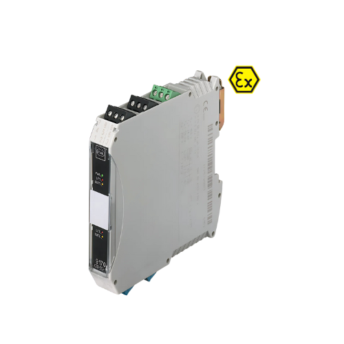


R. STAHL 9170/21-10-11S Switching Repeater
The 9170 series Ex i switching repeaters can be used for operating contacts, NAMUR proximity sensors or optocouplers. [cite: 1] Models are available with one or two channels. [cite: 2] The intrinsically safe digital input is always galvanically separated from the output and auxiliary power. [cite: 2] The channels in the two-channel devices are galvanically separated. [cite: 3] Certain variants transmit frequencies of up to 10 kHz and the output signal can be inverted. [cite: 4]
Technical Data
| Feature | Value |
|---|---|
| Application range (zones) | 2 |
| Ex interface zone | 0, 1, 2, 20, 21, 22 |
| IECEX gas certificate | IECEX BVS 09.0041 X |
| IECEx gas explosion protection | Ex ec nC [ia Ga] IIC T4 Gc |
| IECEx dust certificate | IECEX BVS 09.0041 X |
| IECEx dust explosion protection | [Ex ia Da] IIIC |
| IECEx firedamp certificate | IECEX BVS 09.0041X |
| IECEx firedamp protection | [Ex ia Ma] I |
| gas certificate ATEX | DMT 02 ATEX E 195 X |
| gas explosion protection ATEX | II 3 (1) G Ex ec nC [ia Ga] IIC T4 Gc |
| dust certificate ATEX | DMT 02 ATEX E 195 X |
| dust explosion protection ATEX | II (1) D [Ex ia Da] IIIC |
| firedamp certificate ATEX | DMT 02 ATEX E 195 X |
| ATEX firedamp protection | I (M1) [Ex ia Ma] I |
| FMus certificate | FM16US0122X |
| CFM certificate | FM16CA0067X |
| Marking cFMus Certificates | Class I, Div. 2, Groups A,B,C,D; Class I, Zone 2, Group IIC AIS Class I,II,III, Div. 1, Groups A,B,C,D,E,F,G; Class I, Zone 0, [AEx ia]/[Ex ia] IIC T4 at Ta=70 See Doc. 91 706 02 31 1 ATEX (BVS), Brazil (ULB), Canada (FM), China (NEPSI), IECEx (BVS), India (PESO), Korea (KGS), SIL (exida), USA (FM) |
| Ship approval | CCS, EU RO MR (DNV) |
| Declaration of conformity | ATEX (EUK), China (CCC) |
| Installation | In Zone 2, Division 2 and safe areas |
| Further information | see respective certificate and operating instructions |
| Safety Data Max. voltage $U_{*}/V_{*}$ | 9.6 V |
| Max. current $\Pi_{o}/I_{ac}$ | 10 mA |
| Max. power $P_{o}$ | 24 mW |
| Max. permissible external capacitance $C/C_{a}$ for IIC | $3.6~\mu F$ |
| Max. permissible external inductance $L_{0}/La$ for IIC | 350 mH |
| Max. permissible external capacitance C/C for IIB | $26~\mu F$ |
| Max. permissible external inductance L/Lafor IIB | 1000 mH |
| Max. perm. ext. capacit. IIIC Max. permis. ext. induct. IIIC | $26~\mu F$ 1000 mH |
| Max. permissible external inductance L for I | 1000 mH |
| Max. voltage Uo parallel | 9.6 V |
| Max. current lo parallel | 20 mA |
| Max. power Po parallel | 48 mW |
| Safety-related max. voltage | 253 V |
| Functional Safety Further information | See safety manual and test report |
| Electrical Data Number of channels | 2 |
| LFD relay | Yes |
| Max. short-circuit current | 8.2 mA |
| Auxiliary Power Auxiliary power | 24 V DC |
| Auxiliary power voltage range | 18… 31.2 V |
| Voltage range residual ripple | $\le3,6~V_{ss}$ |
| Nominal current | 55 mA |
| Power consumption | 1.3 W |
| Max. power dissipation | 1.3 W |
| Polarity reversal protection | Yes |
| Undervoltage monitoring | Yes |
| Operation indication | LED |
| Galvanic Isolation Test voltage as per standard EN IEC 60079-11 Ex i input to output | 1.5 kV AC |
| Ex i input to auxiliary power | 1.5 kV AC |
| Ex i input to fault message contact | 1.5 kV AC |
| Ex i input to Ex i input | 500 V AC |
| Test voltage as per standard EN 50178 Output to auxiliary power | 1,1 kV AC |
| Output to output | 1,1 kV AC |
| Fault message contact to auxiliary power | 350 V AC |
| Fault message contact to output | 1,1 kV AC |
| Input Input signal | As per EN 60947-5-6 (NAMUR) |
| Input current for ON | $\ge2.1~mA$ |
| Input current for OFF | $\le1.2~mA$ |
| Hysteresis | Approx. 0.2 mA |
| Input internal resistance R | 1000 Ω |
| Input for open-circuit voltage U | 8,2 V |
| Short-circuit current | ≤ 8.2 mA |
| Output Output per channel | 1 change-over contact – signal relay |
| Output | Change-over contact – signal relay |
| Min. output load condition | $1~V/0.1~mA$ |
| Max. output DC load condition | 125 V/1A |
| Max. output AC load condition | 125 V/1A |
| Output switching capacity | 25 W/50 VA |
| Output switching frequency | 15 Hz |
| Switching delay ON/OFF | 5 ms |
| Switching delay OFF/ON | 5 ms |
| INV switch user adjustment | Activated/deactivated |
| Output electrical service life | $5\times10^{5}$ at 24 V/1 A Resistive load |
| Electrical service life note | $1\times10^{z}$ operating cycles ≤F1A AC/DC |
| Output mechanical service life | |
| Recommended back-up fuse | |
| Switching state indication | LED |
| LF switch user adjustment | Activated/deactivated |
| Wire breakage error detection input | $I_{E}<0.05$ to 0.35 mA |
| Short circuit error detection input | $R_{E}<100$ to 360 ohm OFF |
| Behaviour of output during LF | LED |
| Line fault indication | |
| Fault message contact switching capacity | $30~V/100~mA$ |
| Line fault and loss of power signalization | Contact (30 V/100 mA) closed to ground in case of fault pac-Bus, floating contact $(30~V/100~mA)$ |
| Ambient Conditions Ambient temperature °C | $-20^{\circ}C….+70^{\circ}C$ (Single device) $-20^{\circ}C…+60^{\circ}C$ (Group assembly) |
| Ambient temperature °F | $-4^{\circ}F…+158^{\circ}F$ (Single device) $-4^{\circ}F…+140^{\circ}F$ (Group assembly) |
| Note | Installation conditions influence the ambient temperature. Please observe the “Cabinet installation guide”. |
| Storage temperature °C | $-40^{\circ}C….+80^{\circ}C$ |
| Storage temperature °F | $-40^{\circ}F….+176^{\circ}F$ |
| Max. relative humidity | 95% |
| Use at the height of | < 2000 m |
| Electromagnetic compatibility | Tested to the following standards and regulations: EN 61326-1 For use in industrial areas; NAMUR NE 21 |
| Mechanical Data Degree of protection (IP) | IP30 |
| Degree of protection (IP) terminals | IP20 |
| Fire resistance (UL 94) | VO |
| Enclosure material | Polyamide |
| Grid dimension | 17.6 mm |
| Width | 17.6 mm |
| Width, inches | 0.69 in |
| Height | 114.5 mm |
| Height in inches | 4.51 in |
| Length | 108 mm |
| Length in inches | 4.25 in |
| Weight | 225 g |
| Weight | 0.5 lb |
| Mounting/Installation Mounting type | DIN rail NS35/15, NS35/7.5 |
| Mounting orientation | Vertical Horizontal |
| Connection type | Screw terminal |
| Min. rigid conductor cross section | $0.2~mm^{2}$ |
| Max. rigid conductor cross section | $2.5~mm^{2}$ |
| Min. flex conductor cross section | $0.2~mm^{2}$ |
| Max. flex conductor cross section | $2.5~mm^{2}$ |
| Connection cross-section AWG | 24… 14 |
Accessories
| Accessory | Art. No. | Description |
|---|---|---|
| Resistive coupling element | 247644 | Additional connection of contacts also in hazardous areas to enable short-circuit and wire breakage detection. Mounting on DIN rail. |
| 105944 | Additional connection of contacts also in hazardous areas to enable short-circuit and wire breakage detection YOKO |
Disclaimer: We reserve the right to make alterations to the technical data, dimensions, weights, designs and products available without notice. [cite: 27] The illustrations cannot be considered binding. [cite: 28]